Making a CHIP-8 Emulator in C
CHIP-8 is a simple virtual machine designed in the 1970s for creating games on early computers and gaming consoles. It is notable for its small instruction set and straightforward memory layout, making it suitable for beginners to emulation.
Specifications
- Memory: 4KB of RAM
- Display: 64×32 pixels
- Program Counter (PC)
- Index Register (I): 16-bit
- A delay timer: 8-bit
- A sound timer: 8-bit
- A stack for 16-bit addresses
- 16 variable registers (8-bit) called V0 to VF
Implementing Specifications
#ifndef CHIP_8
#define CHIP_8

#include <stdint.h>

uint8_t  memory[4096];
uint8_t  display[64 * 32];
uint8_t  V[16];  // Registers
uint16_t I;
uint16_t PC;
uint8_t  delayTimer;
uint8_t  soundTimer;
uint16_t stack[16];
uint16_t sp;
uint8_t  keyboard[16];
uint8_t  fonts[80] =
{
    0xF0, 0x90, 0x90, 0x90, 0xF0, // 0
    0x20, 0x60, 0x20, 0x20, 0x70, // 1
    0xF0, 0x10, 0xF0, 0x80, 0xF0, // 2
    0xF0, 0x10, 0xF0, 0x10, 0xF0, // 3
    0x90, 0x90, 0xF0, 0x10, 0x10, // 4
    0xF0, 0x80, 0xF0, 0x10, 0xF0, // 5
    0xF0, 0x80, 0xF0, 0x90, 0xF0, // 6
    0xF0, 0x10, 0x20, 0x40, 0x40, // 7
    0xF0, 0x90, 0xF0, 0x90, 0xF0, // 8
    0xF0, 0x90, 0xF0, 0x10, 0xF0, // 9
    0xF0, 0x90, 0xF0, 0x90, 0x90, // A
    0xE0, 0x90, 0xE0, 0x90, 0xE0, // B
    0xF0, 0x80, 0x80, 0x80, 0xF0, // C
    0xE0, 0x90, 0x90, 0x90, 0xE0, // D
    0xF0, 0x80, 0xF0, 0x80, 0xF0, // E
    0xF0, 0x80, 0xF0, 0x80, 0x80  // F
}

#endif
CHIP-8’s index register and program counter can only address 12 bits, which is 4096 addresses. All the memory is RAM and should be writable. CHIP-8 programs are loaded into memory at address 200. We will simply leave the initial space empty, except for loading the font. By convention the font is set at addresses 050-09F.
Initial state
After setting all the necessary variables, we write a function to set the initial state:
#include <stdio.h>
#include <stdlib.h>
#include <stdint.h>
#include <SDL2/SDL.h>
#include "chip8.h"

void initChip8();

int main(int argc, char** argv)
{
    initChip8();
    return 0;
}

void initChip8()
{
    memset(memory, 0, 4096);
    memset(display, 0, 64 * 32);
    memset(V, 0, 16);
    I = 0;
    PC = 0x200;  // 0x000 to 0x1FF is used by CHIP-8
    delayTimer = 0;
    soundTimer = 0;
    memset(stack, 0, 16);
    sp = 0;
    memset(keyboard, 0, 16);
    memcpy(memory + 0x50, fonts, 80 * sizeof(uint8_t));
}
Loading ROMs
We also need a way to load ROMs. A good resource for CHIP-8 ROMs is the following:
https://github.com/kripod/chip8-roms
We then write a function that can load the ROMs:
int loadROM(const char* filepath)
{
    FILE* infile = fopen(filepath, "rb");
    if (infile == NULL)
    {
        fprintf(stderr, "Couldn't open ROM: %s\n", filepath);
        return 1;
    }

    fseek(infile, 0, SEEK_END);
    int size = ftell(infile);
    fseek(infile, 0, SEEK_SET);

    fread(memory + 0x200, sizeof(uint16_t), size, infile);
    return 0;
}
Make sure to include this function in main:
int main(int argc, char** argv)
{
    initChip8();
    loadROM("roms/ibm-logo.ch8");
    return 0;
}
For now we will load the ibm-logo.ch8 ROM, since it requires very few opcodes and is a good starting point to check if everything is working correctly.
Instructions
To test the ibm-logo.ch8 ROM we will need the following instructions:
00E0(clear screen)1NNN(jump)6XNN(set registerVX)7XNN(add value to registerVX)ANNN(set index registerI)DXYN(display/draw)
We begin by declaring an opcode variable in the chip8.h header file:
uint16_t opcode;Then we implement a function to execute the instructions:
void execute()
{
    uint8_t  X, Y, nn, n;
    uint16_t nnn;

    // Fetch
    opcode = memory[PC] << 8 | memory[PC + 1];
    PC += 2;

    // Decoding
    X = (opcode & 0x0F00) >> 8;
    Y = (opcode & 0x00F0) >> 4;
    n = (opcode & 0x000F) >> 2;
    kk = (opcode & 0x00FF);
    nnn = (opcode & 0x0FFF);
    printf("Opcode: %x\n", opcode);
    printf("Program Counter: %x\n", PC);
    printf("I: %x\n", I);
}
Using SDL2 for rendering
For creating a window and rendering to the screen we will use SDL2. We set up a simple SDL2 loop in the main function:
int main(int argc, char** argv)
{
    if (SDL_Init(SDL_INIT_EVERYTHING) != 0)
    {
        fprintf(stderr, "Failed to initialize SDL: %s\n", SDL_GetError());
        return 1;
    }
    window = SDL_CreateWindow("CHIP-8", SDL_WINDOWPOS_UNDEFINED, SDL_WINDOWPOS_UNDEFINED, 640, 320, SDL_WINDOW_SHOWN);
    if (!window)
    {
        fprintf(stderr, "Failed to create SDL window: %s\n", SDL_GetError());
        return 1;
    }
    renderer = SDL_CreateRenderer(window, -1, SDL_RENDERER_ACCELERATED | SDL_RENDERER_PRESENTVSYNC);
    if (!renderer)
    {
        fprintf(stderr, "Failed to create SDL renderer: %s\n", SDL_GetError());
        return 1;
    }
    SDL_RenderSetLogicalSize(renderer, 64, 32);
    SDL_SetRenderDrawColor(renderer, 0, 0, 0, 255);
    SDL_RenderClear(renderer);
    screen = SDL_CreateTexture(renderer, SDL_PIXELFORMAT_RGBA8888, SDL_TEXTUREACCESS_STREAMING, 64, 32);

    initChip8();
    if (loadROM("roms/ibm-logo.ch8") != 0)
    {
        cleanupSDL();
        return 1;
    }

    uint8_t running = 1;
    SDL_Event event;
    while (running)
    {
        while (SDL_PollEvent(&event))
        {
            switch (event.type)
            {
                case SDL_QUIT:
                    running = 0;
                    break;
                case SDL_KEYDOWN:
                    switch (event.key.keysym.sym)
                    {
                        case SDLK_ESCAPE:
                            running = 0;
                            break;
                    }
            }
        }
        execute();
        draw();
    }
    cleanupSDL();
    return 0;
}
The cleanupSDL function simply destroys the window and renderer created by SDL:
void cleanupSDL()
{
    SDL_DestroyTexture(screen);
    SDL_DestroyRenderer(renderer);
    SDL_DestroyWindow(window);
    SDL_Quit();
}
Finally we need to decode the opcodes. We do this in the execute function. This will just be a big switch statement that will get even bigger once we implement the rest of the opcodes. The execute function looks like this now:
void execute() {
    uint8_t  X, Y, kk, n;
    uint16_t nnn;

    X = (opcode & 0x0F00) >> 8;
    Y = (opcode & 0x00F0) >> 4;
    n = (opcode & 0x000F);
    kk = (opcode & 0x00FF);
    nnn = (opcode & 0x0FFF);
    printf("Opcode: %x\n", opcode);
    printf("Program Counter: %x\n", PC);
    printf("I: %x\n", I);

    switch (opcode & 0xF000)
    {
        case 0x0000:
            switch (opcode & 0x00FF)
            {
                case 0x00E0:
                    memset(display, 0, 64 * 32);
                    break;
            }
            break;
        case 0x1000:
            PC = nnn;
            break;
        case 0x2000:
            break;
        case 0x3000:
            break;
        case 0x4000:
            break;
        case 0x5000:
            break;
        case 0x6000:
            V[X] = kk;
            break;
        case 0x7000:
            V[X] += kk;
            break;
        case 0x8000:
            break;
        case 0x9000:
            break;
        case 0xA000:
            I = nnn;
            break;
        case 0xB000:
            break;
        case 0xC000:
            break;
        case 0xD000:
            uint8_t x = V[X] % 64;
            uint8_t y = V[Y] % 32;
            uint8_t pixel;

            V[0xF] = 0;
            for (int i = 0; i < n; i++)
            {
                pixel = memory[I + i];
                for (int j = 0; j < 8; j++)
                {
                    if ((pixel & (0x80 >> j)) != 0)
                    {
                        if (display[x + j + (y + i) * 64] == 1)
                        {
                            V[0xF] = 1;
                        }
                        display[x + j + (y + i) * 64] ^= 1;
                    }
                }
            }
            drawFlag = 1;
            break;
        case 0xE000:
            break;
        case 0xF000:
            break;
    }
}
Don’t forget to add drawFlag to the chip8.h header file:
uint8_t drawFlag;Finally, we implement the draw function:
void draw()
{
    uint32_t     pixels[64 * 32];
    unsigned int x, y;

    if (drawFlag)
    {
        memset(pixels, 0, (64 * 32) * 4);
        for (x = 0; x < 64; x++)
        {
            for (y = 0; y < 32; y++)
            {
                if (display[x + (y * 64)] == 1)
                {
                    pixels[x + (y * 64)] = UINT32_MAX;
                }
            }
        }

        SDL_UpdateTexture(screen, NULL, pixels, 64 * sizeof(uint32_t));

        SDL_Rect pos;
        pos.x = 0;
        pos.y = 0;
        pos.w = 64;
        pos.h = 32;
        SDL_RenderCopy(renderer, screen, NULL, &pos);
        SDL_RenderPresent(renderer);
    }
    drawFlag = 0;
}
Keyboard Mapping
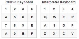
We will add one more feature with the help of SDL2: capturing input. The computers used with CHIP-8 had hexadecimal keypads. That means they only had 16 keys (0 through F) in a 4×4 grid. By convention these are mapped to the left side of QWERTY keyboards:

This is just a matter of capturing each SDL keypress:
                        case SDLK_ESCAPE:             // This was already here
                            running = 0;              // This was already here
                            break;                    // This was already here
                        case SDLK_1:
                            keyboard[0x1] = 1;
                            break;
                        case SDLK_2:
                            keyboard[0x2] = 1;
                            break;
                        case SDLK_3:
                            keyboard[0x3] = 1;
                            break;
                        case SDLK_4:
                            keyboard[0xC] = 1;
                            break;
                        case SDLK_q:
                            keyboard[0x4] = 1;
                            break;
                        case SDLK_w:
                            keyboard[0x5] = 1;
                            break;
                        case SDLK_e:
                            keyboard[0x6] = 1;
                            keyboard[0x6] = 1;
                            break;
                        case SDLK_r:
                            keyboard[0xD] = 1;
                            break;
                        case SDLK_a:
                            keyboard[0x7] = 1;
                            break;
                        case SDLK_s:
                            keyboard[0x8] = 1;
                            break;
                        case SDLK_d:
                            keyboard[0x9] = 1;
                            break;
                        case SDLK_f:
                            keyboard[0xE] = 1;
                            break;
                        case SDLK_z:
                            keyboard[0xA] = 1;
                            break;
                        case SDLK_x:
                            keyboard[0x0] = 1;
                            break;
                        case SDLK_c:
                            keyboard[0xB] = 1;
                            break;
                        case SDLK_v:
                            keyboard[0xF] = 1;
                            break;
                    }
                    break;
                case SDL_KEYUP:
                    switch (event.key.keysym.sym)
                    {
                        case SDLK_1:
                            keyboard[0x1] = 0;
                            break;
                        case SDLK_2:
                            keyboard[0x2] = 0;
                            break;
                        case SDLK_3:
                            keyboard[0x3] = 0;
                            break;
                        case SDLK_4:
                            keyboard[0xC] = 0;
                            break;
                        case SDLK_q:
                            keyboard[0x4] = 0;
                            break;
                        case SDLK_w:
                            keyboard[0x5] = 0;
                            break;
                        case SDLK_e:
                            keyboard[0x6] = 0;
                            break;
                        case SDLK_r:
                            keyboard[0xD] = 0;
                            break;
                        case SDLK_a:
                            keyboard[0x7] = 0;
                            break;
                        case SDLK_s:
                            keyboard[0x8] = 0;
                            break;
                        case SDLK_d:
                            keyboard[0x9] = 0;
                            break;
                        case SDLK_f:
                            keyboard[0xE] = 0;
                            break;
                        case SDLK_z:
                            keyboard[0xA] = 0;
                            break;
                        case SDLK_x:
                            keyboard[0x0] = 0;
                            break;
                        case SDLK_c:
                            keyboard[0xB] = 0;
                            break;
                        case SDLK_v:
                            keyboard[0xF] = 0;
                            break;
                    }
                    break;
            }
        }
        execute()                      // This was already here
        draw()                         // This was already here
Running the ibm-logo ROM
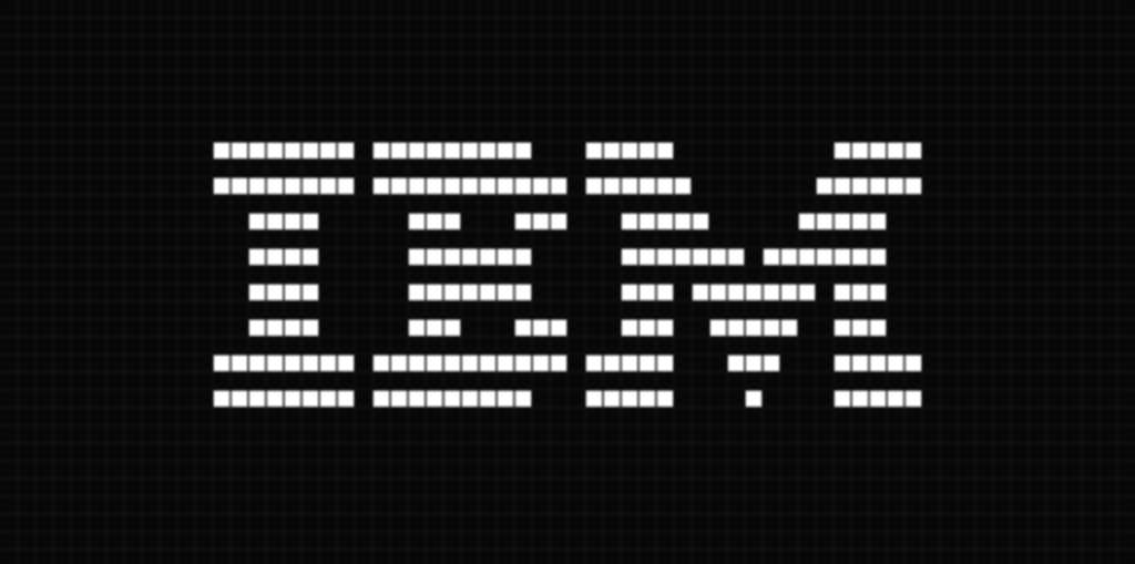
At this point our program has everything we need to run the ibm-logo.ch8 ROM. If we test it out, we see the following:

That’s it for now. You can check out the rest of my code on my GitHub profile:
https://github.com/ssilatel/chip8
There you can find the implementation of the rest of the opcodes as well as adding a timer.
Thank you for reading!